
Saturday 8 August 2026 · David Toms, President
Rebuilding a wicking bed
Three and a half cubic metres of soil, a metre and a half of gravel, and a good deal more work than anyone expects. What it actually takes to rebuild a wicking bed from the bowling green up.
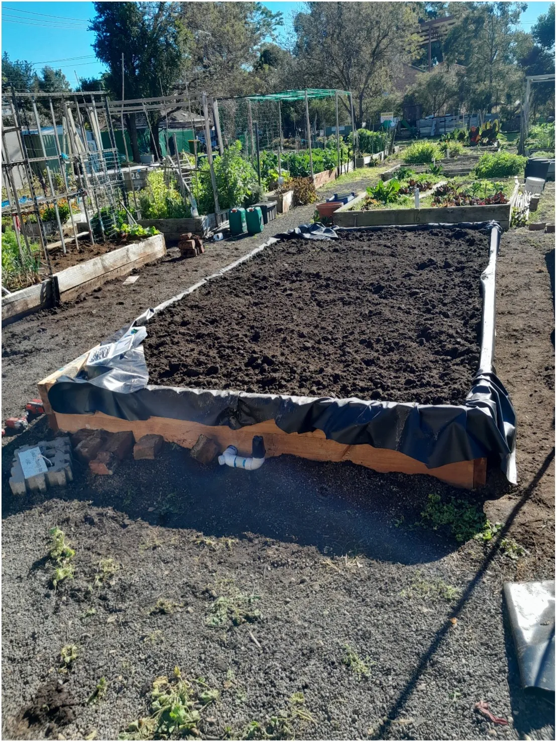
This seems, on the surface, a simple task. It surprises most members just how much work is required to complete it.
Where does the soil go?
Clearly the first job is to remove the soil, and that is about 3.5 cubic metres of it. Task one: where to put it.
Most of MEG’s plots have about a metre between them, so the soil has to be moved by wheelbarrow to a different location until we are ready to put it back. We are currently working on plot 7, which has two sides with at least two metres of space, so it is a lot easier.
Stripping it back
Once the soil is removed, the membrane can come off, exposing the gravel bed and the Agi pipes.
Remove the Agi pipe and the gravel. The 1.5 cubic metres of gravel goes to a different position from the soil, as we do not want the two to mix.
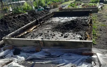
Stripping back: soil out first, then the membrane, then the gravel and Agi pipe.
Once we have cleared the plot, we dismantle the timber structure.
A clean, flat base
The next step is very important: we need a flat, clear surface. Luckily at MEG the old bowling green should now be exposed, and once swept and cleaned, we can move on.
It should be noted that any stones or rocks left behind can pierce the plastic liner, rendering the whole job useless. If you are building on a site that is just soil, it is well worth putting an old carpet down.
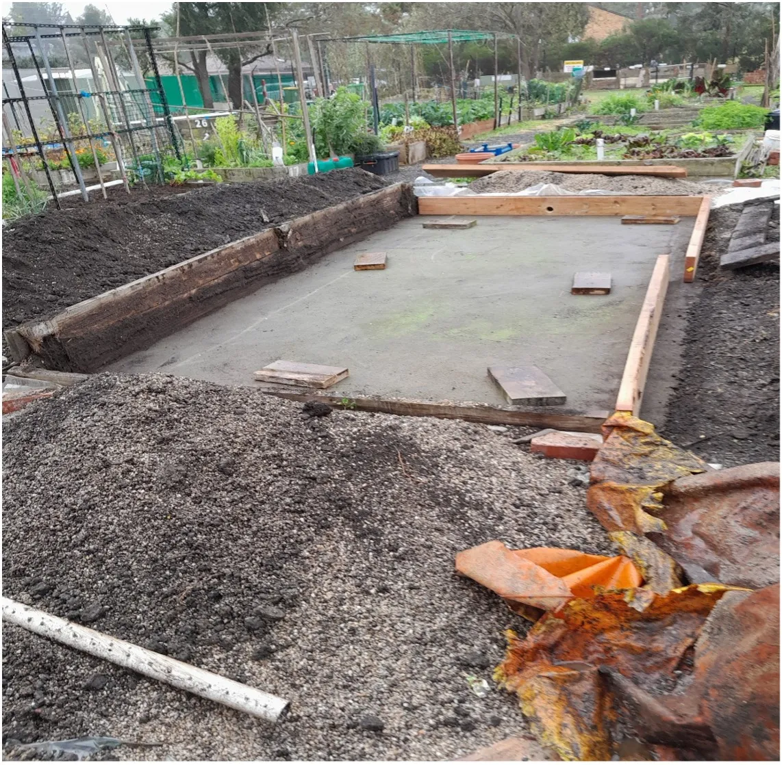
The old bowling green, swept clean, with the new timber going down. Soil to one side, gravel to the other.
Timber and liner
Before installing the timber, we need to bore a hole in two of the timbers, centred width-wise and two thirds of the way down the depth. These holes will take the water feed and the drain point.
Once the timber structure is in place, we can install the plastic liner. It is important to have enough liner to cover the base and all of the sides.
Now the plastic is in place, we return a small amount of gravel internally, around the edges, to weigh it down for a couple of days. This allows the plastic to mould itself into place.
Now is a good time to roll out the Agi pipe. I like the sock-covered pipe, just a personal preference.
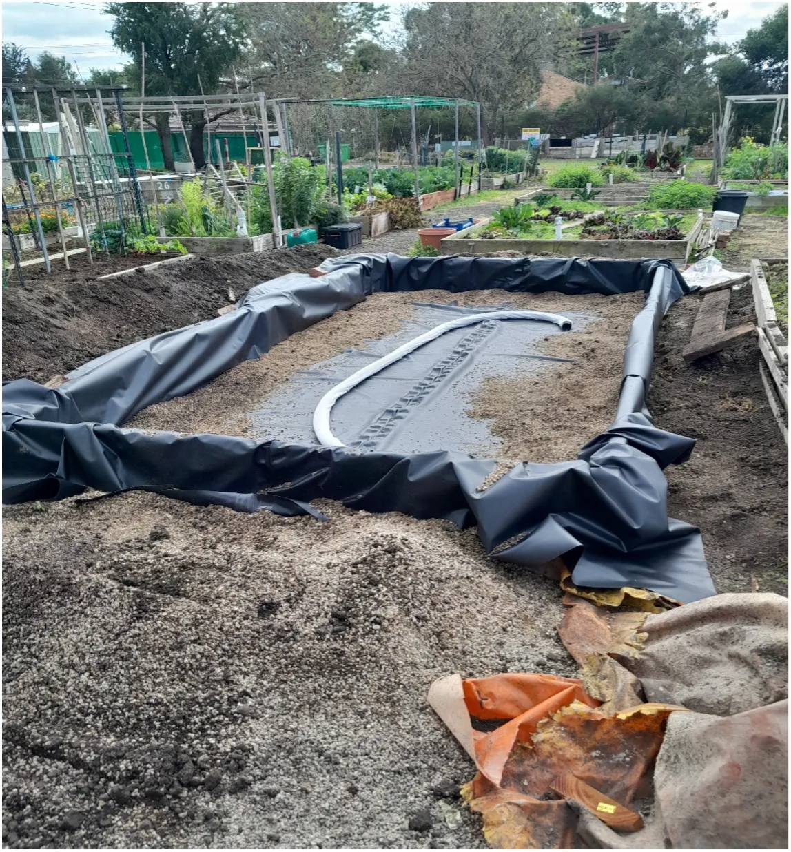
Liner in, gravel around the edges to hold it, and the Agi pipe rolled out ready.
Inlet and outlet
When the plastic has been down for a couple of days, it is time to fix the entry and exit points.
Gently cut a circle in the plastic that corresponds to the holes we bored in the timber. Now insert the plastic flange, which is called a 50 mm safe tray flange. Once we are sure it fits snugly into the hole, we remove it and squeeze plenty of silicone onto the side closest to the wall. Return the flange to the hole, making sure it sits flat against the timber.
Screw at least four screws through the flange into the timber. Finally, silicone around the edge of the flange to ensure no water can penetrate. We then need to wait at least 24 hours for the silicone to cure.
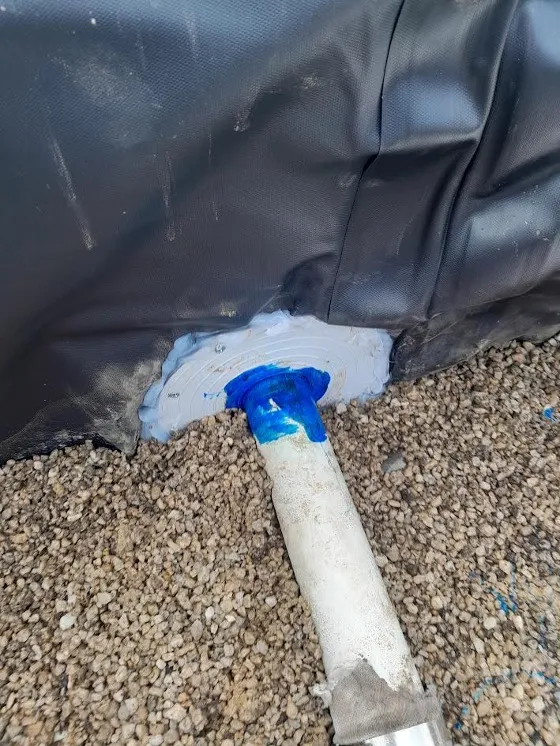
The 50 mm safe tray flange, bedded in silicone, screwed home and sealed around the edge.
The Agi pipe needs to be joined at each end to a short length of 50 mm pipe. At MEG we have found that cutting wedges into the 50 mm pipe allows it to be squeezed into the Agi pipe and secured with a 20 mm worm-drive hose clamp.
The 50 mm pipe exits the plot via the 50 mm flange. Once we are sure of the exact location, wipe the pipe with blue plastic pipe cement.
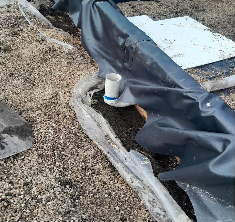
The 50 mm pipe exiting through the flange, cemented in place.
Gravel, membrane, soil
Once dry, we can fill the plot with gravel, enough to at least cover the Agi pipe.
Gravel in, it is time to install the membrane. Cover all of the gravel; none should be exposed.
We can now return the soil to the plot, filling it completely to 50 mm from the top. It is a good idea to mix in any available compost during the process.
Returning to the input and exit points: on the input end we need a 50 mm × 90° bend and a short jump-up pipe.
On the outlet we need a 50 mm × 45° DWV bend to allow for waste water, a very short length of pipe joining the DWV bend to a right-angle bend, and a short jump-up to ensure the water does not drain, unless the bed is too full, in which case it acts as an overflow.
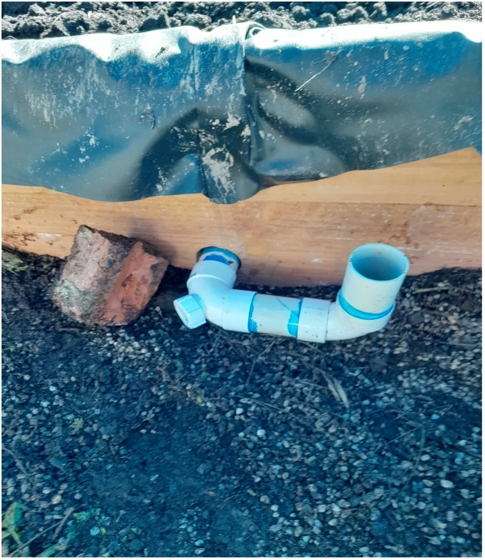
The outlet assembly: 45° DWV bend, a short length of pipe, a right-angle bend and the jump-up that doubles as the overflow.
Finishing the edge
Lastly, after a week the soil should have settled, and we can install an edge strip around the top, securing the plastic liner. Cut off the excess liner. A coat of paint on the edge strip is worthwhile to add longevity to the plot.
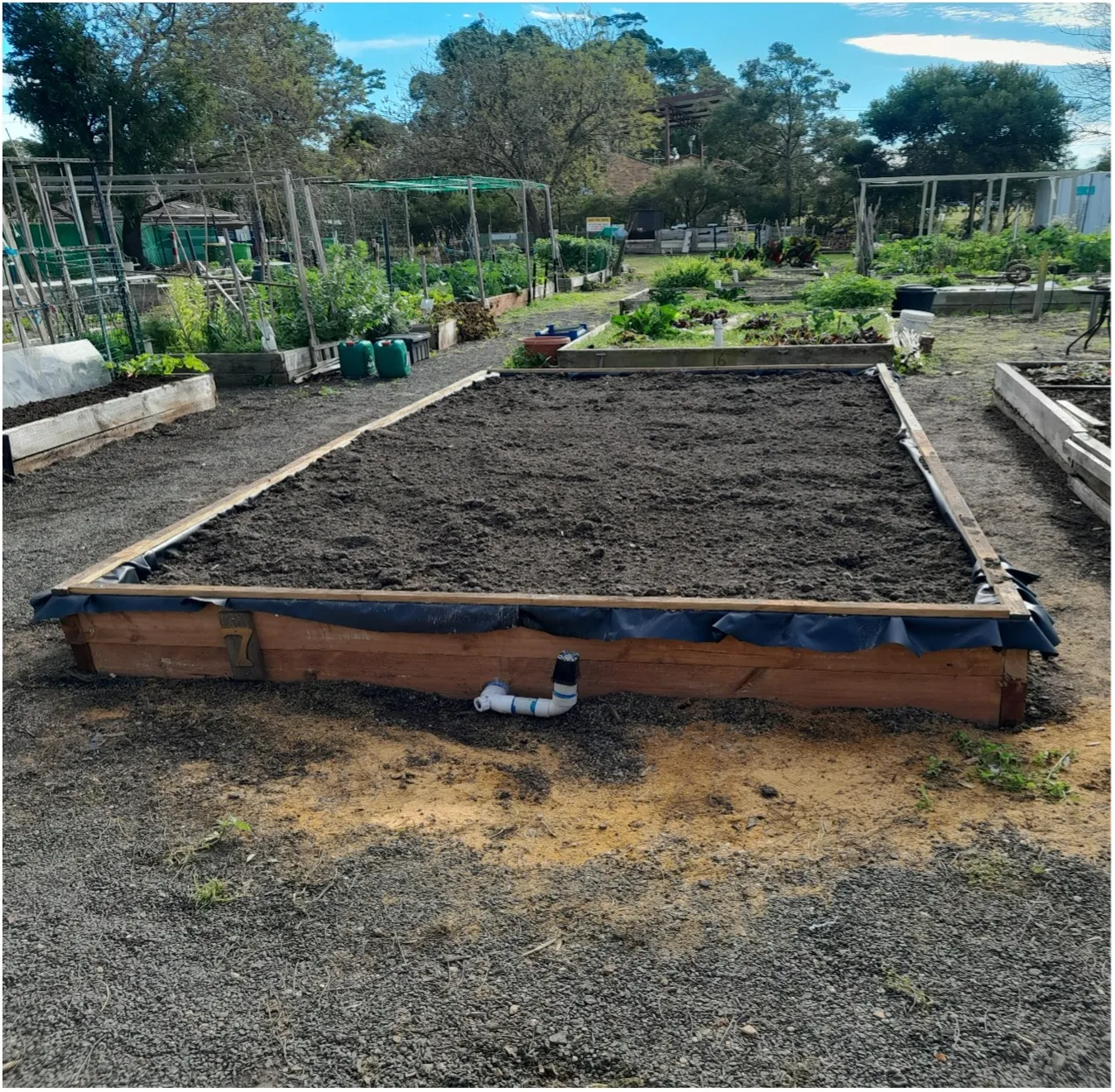
The finished plot.